Mixing is the process of converting multiple Tracks into a Stereo Mix where all the instruments can be heard clearly.
Mixing Tools
Levels, Panning, Equalization (EQ), and Compression are the main tools used to achieve a good Mix. In addition to these core tools, a wide range of Plugin effects can also be used to enhance the sound, such as Reverb and Delay.
Introducing the Mixer Strip
The Mixer Strip is the vertical column that contains various controls related to signal flow. Each Track and Bus in Ardour has its own Mixer Strip. The Mixer Strip is also the main tool we will use in the process of Mixing our Tracks. In this chapter, we will get a general overview of the Mixer Strip, with each section described. We will also provide references to chapters containing information specific to each aspect of the Mixer Strip.
The Mixer Strip from Top to Bottom
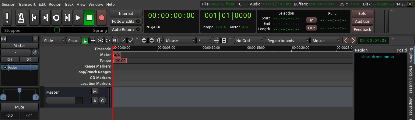
Mixer Strips can be accessed from both the Editor Window and the Mixer Window (shortcut “Alt” + “M” to toggle between the two). Mixer Strips in either window (Editor or Mixer) mirror each other: any actions performed on a Mixer Strip in the Mixer Window will be reflected in the corresponding Mixer Strip in the Editor Window, and vice-versa. The Editor Window and Mixer Window are more fully explained in the An Overview of the Interface chapter.
In the Editor Window, you can see the Mixer Strip of the currently selected track on the left side of the window. If you don’t see it, hit “Shift” + “E” to display the Editor Mixer Strip.
Overview
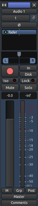
Here we see the entire Mixer Strip, as it would appear in either the Editor Window or the Mixer Window.
Regular & Narrow Modes
The Mixer Strip can be switched between the regular width and a more narrow width to conserve space. The very top part of the Mixer Strip, pictured below, switches between regular and narrow modes using the left button. The right button hides the Mixer Strip entirely.

Track Name and Routing Button
Continuing from top to bottom, the next section of the Mixer Strip contains three narrow regions. The first of these regions shows the name of the Track (that’s the word “clap” in the image below). The next region, named “2” in the image below, is a button which allows access to the input Routing. Please see the Understanding Routing and Recording Audio chapters for more information on input Routing. The last narrow region controls phase reversing (we won’t go into details on this topic in this tutorial).
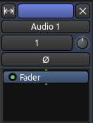
Processor Box
The large black region at the bottom of this section is the Processor Box. This is where you can add Plugins, for example. The processor box will always contain a blue Fader processor. This indicates where in the processor chain the main channel fader is located — this is the fader shown in the lower half of the strip. Please see Using Plugins and Using Sends for a detailed discussion of this area.
The next portion of the Mixer Strip includes controls for Panning, Record, Mute, and Solo, among others.
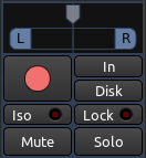
Panning
Panning has to do with placement of sounds anywhere between Left and Right speakers. Please refer to the Panning chapter for more information.
Solo
When a Track or Bus is on Solo, all the other Tracks or Busses which are not likewise on Solo will be inaudible through the Master Bus or the Audition. We can also find a miniaturized Solo Button in the Track Mixer. Note that soloing a bus will not silence any tracks and vice-versa.
When any Track or Bus is on Solo, the Solo Indicator in the Auxiliary Controls menu will flash red. Clicking the Solo Indicator while it is flashing will deactivate every Solo in the Session.
Mute
Any Track or Bus on Mute will be inaudible through the Master Bus or the Audition. The Track Mixer also contains a miniaturized Mute Button, in between the Record Arm Button and the Solo Button. Right-Clicking on the Mute Button gives you advanced options for the behavior of the mute button.
Arm Record
The Rec button arms the track for recording, as seen in the Recording Audio chapter.
Fader, Fade/Peak Meters
The most prominent control present in a Mixer Strip is the Fader, used to adjust the overall gain for the corresponding Track or Bus. The Peak Meter shows the Peak Value of the selected track, and is located directly to the right of the Fader. Each Peak Meter consists of one Bar Graph in the case of a Mono Track, and two Bar Graphs in case of a Stereo track. The small rectangular field above the meters shows the highest Peak Value that has been played on that track so far.
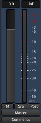
By clicking the right-hand button at the bottom of the Mixer Strip (it reads “post” in the image above), you will be able to select the Metering Point, for example the direct “in” from the sound card, the “pre” Fader signal, or the “post” fader signal.
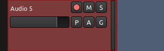
As you can see in the image below, there is a smaller version of the Mixer Strip in each Track, called the Track Mixer, which contains a horizontal Fader, a vertical Peak Meter as well as miniature buttons for Arm Record, Mute, and Solo. They all mirror those found in the Mixer Strip for that Track.
Please refer to the chapter on Mixing Levels for more detailed instruction about using the Fader and Peak Meters.
Routing
Finally, we reach the bottom of the Mixer Strip. Here we find the Output Routing Button, marked as “master” in the earlier screenshot, which is discussed in the Understanding Routing chapter.
Continuing
Now that we’ve had a look at the main areas of the Mixer Strip, we can proceed to the Mixing Levels chapter to see how we can start to use it.
Next: MIXING LEVELS